This article will discuss headlight beam patterns and the standards that agencies such as ECE/DOT require. The following points will be addressed to help gain a better understanding:
- What does the original ECE front headlight testing graphic look like?
- The original ECE front headlight testing graphic combine with driveway image
- Some testing points that need to pay more attention to
- Other standards used in other countries and areas (SAE/ADR)
How do we define a safe and effective headlight beam pattern and what are the standards it has to meet? Most people would say they want a headlight that is super bright, covers a large area in front of the vehicle and has uniform illumination with no dark spots. But can this be achieved and still meet the standards set forth by ECE (E-mark) or SAE (DOT)?
The short answer is, YES! The keys to optimal performance are to be sure the light is focused in the proper position and it does not create glare or a safety hazard for oncoming traffic. Quite simply, this is the definition of an acceptable light beam pattern, but there is much more technical information behind the standard.
Let’s have a look at the RHT (right hand traffic) ECE light beam pattern graphic that defines the standard.

It is quite complicated at first glance, right?
Each point and line on the graphic are key to establishing an acceptable pattern for headlights. Let’s break this down so we can understand the graphics and the standard.
This is the traditional view you will have while driving on a single-lane road:

Let’s combine the drivers view with the ECE testing graphic. If the headlight is properly aimed (yellow dot with red border) we can now see heights and angles determined by the ECE that determine the correct and safest pattern for a headlight beam. Notice the data points are intentionally lower than the windshield of the oncoming vehicle, except for one.

There are two distinct lines that define the V and H axis: the Vertical line (V) and the Horizontal line (H). The V represents the centerline of the vehicle’s heading. The H represents the horizon line for the top of a headlight beam pattern. The ECE additional data points are intentionally placed within the area that the headlight beam will be illuminating. Each data point indicates an area to be measured during testing.
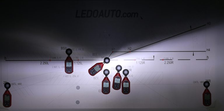
Now that we have a general understanding of the above image, we can look at the data points in the ECE standard one by one. In general, there is a horizontal line and an angled 15 degrees oblique line that forms a clear horizon line in the ECE standard graphics. There are many data points and lines in the ECE standard graphic, to further understand the graphic, we should look at the 8 main data points (highlighted in red) in the ECE standard. The data points are marked as B50L, 25R, 25L, 50R, 50L, 50V, 75R, 75L.

Each data point represents a separate area of concern. Some of the data points are more important than others. Can you guess which ones? Let’s see if you are correct:
1, B50L test point
The B50L test point represents the position of the oncoming driver’s eyes that are 50 meters from the headlights. If the headlight beam pattern is unfocused and creates a glare, the B50L test point will determine how dangerous the pattern is. Unsafe levels of light at this data point could lead to potential danger for an oncoming vehicle. Blinding light leads to accidents that could prove fatal. According to the ECE standard, the Lux of B50L should be less than 0.4 lux tested in 25 meters distances.
2, 50V test point
In addition to the B50L test point, the 50V data point is also very important. While the B50L measures the safety for oncoming drivers, the data point for 50V measures the brightness at 50 meters in front of the vehicle. The 50V data point naturally will be brighter so it can illuminate ahead of the vehicle at a longer distance. According to the ECE standard, the lux value of 50V should be the highest in order to illuminate ahead of the vehicle, in all driving conditions, while maintaining safety for oncoming traffic.
3, 25R, 25L, 75R & 75L test point
The 25R & 25L (Right & Left) test points measure the furthest points or spread of brightness. Think along the lines of an animal coming out of the woods or a person walking alongside the road. This is where 25R & 25L brightness levels are crucial for the driver and potential hazards on the roadside. Additionally, the 75R and 75L data points measure the spread of brightness closer to the focus point of the headlight. 75R measures the right side of the road shoulder at 75 meters and 75L the left side road shoulder at 75 meters.
The First Example
The lux value of the 50V data point should be the brightest and is potential without limits. If the 75L and 75R test points both have a high lux value, it can be assumed that it is safer for the driver to see down road clearly. We can also assume this would help avoid any potential road hazards. Think of driving in a city environment. You want to see what is directly ahead of you, but you also need to see damaged areas of the road and potential obstacles that may appear from either side of the lane you are in.

The Second Example
Now that we know that we can see at a distance of 75 meters ahead of the vehicle, within the defined driving lane we are in, what about the unexpected objects that may appear directly in front of us? The lux values at the 25R and 25L (25 meters) data points are very important for determining overall safety. If you cannot see that pedestrian or animal making their way onto the roadway you are driving on, you will most likely harm them or yourself. So, the data points at 25L and 25R are very important for determining the proper brightness to allow the driver to see any potential hazards.

Now that we know the RHT ECE standard and the data points on the graphic, we can understand why headlights need to meet safety standards. But what about the rest of the world? Do they comply with the ECE standard? There is the Commonwealth of Nations, Australia, Japan and let’s not forget the drivers who drive on the opposite side of the road. How do they measure a safe and standardized light beam pattern?
The reality is, ECE standard has a measure for left hand drive traffic (LHT). The difference between LHT and RHT is that the test points and the lines are reversed. The LHT is an inverted graphic to the RHT.
Actually, ECE still has left hand traffic standard (LHT). The difference between LHT and RHT is that the test points and the lines are opposite. In short, the LHT is contrary to the RHT.
ADR standard
In Australia, they adhere to the ADR standard. It is similar to the LHT ECE standard.

SAE standard
The other standard for front headlight rules is the SAE (DOT) standard. It is different from the ECE standard. DOT standard is tested in a distance over than 18.3 inches, it requires a wide light beam. The SAE test point 12, point 13, point 14 and point 15 are wider which ECE is not required.

Although SAE is different from ECE, it still similar to ECE RHT. That is:
- 50V in ECE = SAE point 7
- 50L in ECE ≈ SAE point 8
- 25L in ECE ≈ SAE point 10
- 25R in ECE ≈ SAE point 11
- B50L in ECE is in the SAE line 4
DOT standard required a wide light beam, there are more test points than ECE. The dark spot of SAE requires more test points. The hotspot of test points is closer than ECE.
CONCLUSION
The light beam pattern standard introduced today is suitable for the low beam, the high beam has different standards.

